
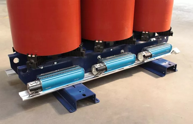
Forced ventilation systems produced by Power consist of 4, 6 or 12 air-cross fans according to the power range and dimensions of the unit. They are delivered completely assembled and wired and can be easily mounted on different transformer brands.
We recommend using forced cooling systems together with temperature relays PWR07 or PWR08 (suitable for PT100 or PTC sensors), which monitor temperature inside the windings and switch on and off the forced ventilation when necessary, as well as controlling device PWR12, which diagnoses motor faults in the ventilation system by detecting current changes.
Forced ventilation by Power copes perfectly with the two major problems appearing in transformer installations:
- Providing overheat protection of the transformer during hot spells
- Increasing the transformer’s capacity in the periods of peak energy demand.
Forced cooling is also highly recommended in case of:
- Short-time overloadings
- Small size installation room
- Poorly ventilated installation room
- Medium daily temperature higher than 30°C
Please consider that medium operation life of each ventilation system is around 20.000 hours. The life of your cast resin transformer are 25 -30 years. Make sure to maintain the cooling fans correctly and to replace them in time, if necessary.
Forced ventilation can be fitted at Manufacturer’s works or after installation of the transformer at site. Please consult Figures 11 and 12 and Table 3 different models capacity and dimensions.
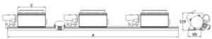
Figure 11 – Tangential ventilation bar (front view)
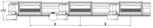
Figure 12 – Tangential ventilation bar drawings (top view)
| Model | Power range (kVA) | Airflow (m3/h) | A (mm) | B (mm) | C (mm)/th> |
|---|---|---|---|---|---|
| PWF1200/A | 50 | ~1200 | 1400 | Till 330 | 225 |
| PWF1200/B | 100 – 630 | ~1200 | 1400 | 340-460 | 225 |
| PWF1200/C | 800 – 1000 | ~1200 | 1600 | 470-540 | 225 |
| PWF1800/A | 1250 – 1600 | ~1800 | 1850 | 550-590 | 405 |
| PWF1800/B | 2000 | ~1800 | 2000 | 600-650 | 405 |
| PWF3600 | 2500 – 3150 | ~3600 | 2200 | 660-730 | 545 |